

Solid networking fundamentals is now a primary required skillset for a systems integrator. Technicians who master these fundamentals will advance their careers more quickly than those who struggle along. Companies that provide educational material will see their technicians become more efficient, and more frequently solve problems at the root cause.
This guide is written to be educational material for residential AV technician who deploy networks, surveillance systems, and control platforms. The detail it provides is intended to be enough to create a solid understanding of how networks work without providing so much detail that the core fundamentals are lost. The ultimate goal is to provide maximum education with a minimum time investment.
Join our discord server. I’d love to connect, and to clarify any of these concept. It’s a good place for the integrator to meet, collaborate, and commiserate with other integrators.
Basic Networking Terms
Here are some basic definitions to refer to if there’s a term that you don’t understand.
IP Address: A logical address assigned to a network interface. A network interface does not have an IP address until it has been assigned, either by a person or automatically by another device on the network.
Octet: A segment of an IP address. Every IP address is made of 4 octets, separated by 3 “dots.” For example, in the IP address 192.168.16.4, the first octet is 192, the second octet is 168, the third octet is 16, and the fourth octet is 6.
MAC Address: A physical address permanently attached to a network interface. It is assigned at the factory and cannot be changed.
Subnet Mask: A filter that when applied to a specific IP address will dictate the rest of the IP addresses to be considered as part of the same LAN (local area network). For example, if a device has the IP address of 192.168.16.4 and a subnet mask of 255.255.255.0, then that device wil consider all of the IP addresses from 192.168.16.0-192.168.16.255 as part of the same LAN.
Network Interface: The part(s) of the device that is responsible for making the connection between the device components and network components. It is physical like an RJ45 port or a Wifi chipset, and it has software defined attributes. Every network interface, at a minimum, has an IP address and a subnet mask.
DHCP: The process by which a device obtains an IP address if it is not manually assigned. Read more about the process.
Configuring network interfaces.
This is probably the single most important thing to understand, and it’s where most integrators makes mistakes. First, as a refresher, let’s talk about the range of private IP addresses you can use when setting up a local area network.
192.168.XXX.YYY
10.NNN.XXX.YYY
172.16.XXX.YYY
Since we will only be talking about networks with a subnet mask of 255.255.255.0 (or a 24 bit prefix), the N’s and the X’s can be whatever you like so long as they stay the same throughout the entire entire network. The Y’s will be unique to each device. And of course, only the numbers 1-254 can be used.
The IP spaces listed above constitute the entire list of IP schemes that can be used in a private network. These IP addresses are NOT used in public networks, and are unusable on the WAN side of a router (but more on that later).
There are two methods of assigning IP addresses. One is manual, and the other is automatic. Let’s talk about manual up addressing first.
Static IP Addresses
Static IP addresses are set at the device itself. Usually, the device will have some sort of interface that will ask you for the details on how you want to configure the network interface. Here is an example from Windows 10:
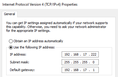
About the different components of the network interface:
- The IP address must be unique. If it is shared with any other device on the network then neither device will work properly.
- The subnet mask defines the scope of the local area network. In our case, it will always be 255.255.255.0.
- The default gateway is the IP address of the router. The default gateway is used to reach devices that are outside the local area network.
Static IP addresses are easy to set, and easy to keep unique so long as the used addresses have been documented.
Automatic IP Addressing – DHCP
DHCP stands for dynamic host configuration protocol. When a device is connected to the network is set to automatically retrieve an IP address, the first thing it does it send out a DHCP request. This request is sent to the entire network, and it waits for a DHCP server to reply.
In most home networks, the DHCP server is the also the router. The router answers this request by assigning an IP address to the device that sent the request, and it also provides other details like subnet mask, the default gateway, and a list of DNS servers to use.
The DHCP server will assign IP addresses from a range of addresses that is specified in it’s configuration. Here’s an example the DHCP configuration on an Araknis router:
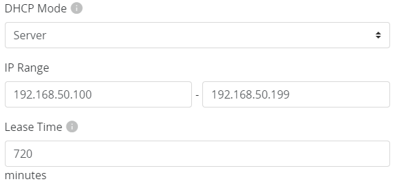
This Araknis router is set to act as the DHCP server, and it will hand out IP addresses between the range of 192.168.50.100 and 192.168.50.199. That’s a total of 100 IP addresses that the router can assign. Once all of the IP addresses are active it will have no more to hand out. This range of IP addresses is called the “DHCP Scope” or sometimes the “DHCP Address Pool.”
Once an address is assigned, the DHCP server will temporarily remove the device from the pool of addresses that it can use. It will return it to the pool of usable IP devices only when the device says that it’s finished with it, or when the lease time expires (which in this case is 720 minutes, or 12 hours).
Shorter lease times (less than a day) are better for networks that will have many devices coming and going because it will return IP addresses to the DHCP pool faster. If the network will mostly see the same devices over and over again, a longer lease time (maybe a week) would be more appropriate.
If the device will need to continue using the IP address for a longer period of time, it must renew it’s IP addresses before the lease time is up. When it does this, it will be given a time extension to use the same IP address.
However, and this is very important:
When a DHCP lease expires or is otherwise lost, it will force the device to request a new address. The new address might be different than the old address. Therefore, DHCP is not recommended when it is imperative a device remain at the same IP address, unless the DHCP server has been configured to reserve that specific IP address for that specific device.
DHCP is an excellent method to hand out IP addresses to network devices. It ensures no two devices will have the same IP, and it requires no special configuration at each device.
DHCP Address Reservations, “Fixed IP,” and Static Leases:
All of these terms have the same meaning. DHCP servers can be set to reserve a specific IP address for a specific device. It has the same benefits as having a static IP, but also the benefits of being able to be assigned automatically, with no configuration at the device itself.
DHCP Servers (which most of the time is the router) usually offer a table where you can input the physical address (MAC Address) of a network interface, and then assign an IP address to be given to to it.
Here is an example from a Luxul Router:
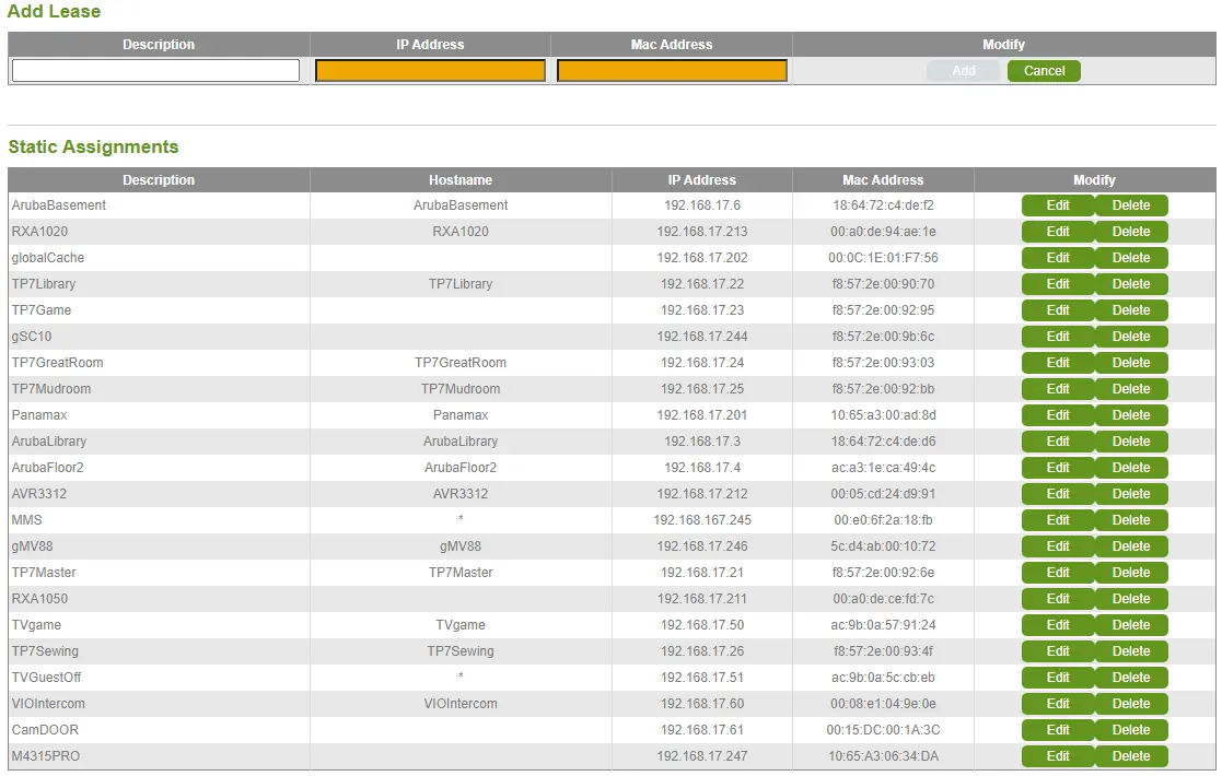
The host name and description in the above example are generally not important. The router will use solely the MAC address to determine what IP a device should be given, and if the MAC address is not part of this list, it will assign an IP address randomly from the regular DHCP pool.
Some routers will not let you make DHCP reservations for addresses that are outside the standard DHCP Scope (comcast routers are like this). However, the router will not assign an other DHCP device to an address that is being reserved, so in this case, keeping a fixed address within the DHCP scope is acceptable.
It is not always appropriate to use a DHCP reservation in lieu of a static IP. A good example is a Wifi based remote control. For the best user experience, these devices need to be able to send communication the very second their display wakes up. If the remote has a static IP, it can start sending messages with no delay. If it has to wait for the DHCP process to complete, there could be a delay ranging from a couple milliseconds up to a couple of seconds.
Planning to prevent conflicting IP Addresses:
The most commonly see integrators creating IP address conflicts because they are setting static IP addresses within the DHCP scope. To which they say to me, “why would the router assign an IP address that’s already been used?”
A router does not keep track of devices on the network in order to avoid handing out duplicate IP addresses.
It may show you a fancy display of all the devices and their connectivity static, but this is just basically a program that runs on the same hardware of your router, but is not at all related to how it functions as a network device.
A router will only keep track of IP addresses it hands out through DHCP, and only keeps track of them for the purpose of not handing out a duplicate. If a device is using a manually assigned IP address within the routers DHCP scope, it’s only a matter of time before the router assigns another device that same IP.
Never assign a static IP addresses within the range of the DHCP Scope.
It’s important to document each network deployment so that it’s easy to look back years later and know the consumption of IP addresses and how the DHCP is allocated.
Here is an example of an excel spreadsheet for a small network. It’s green/black for dramatic effect.
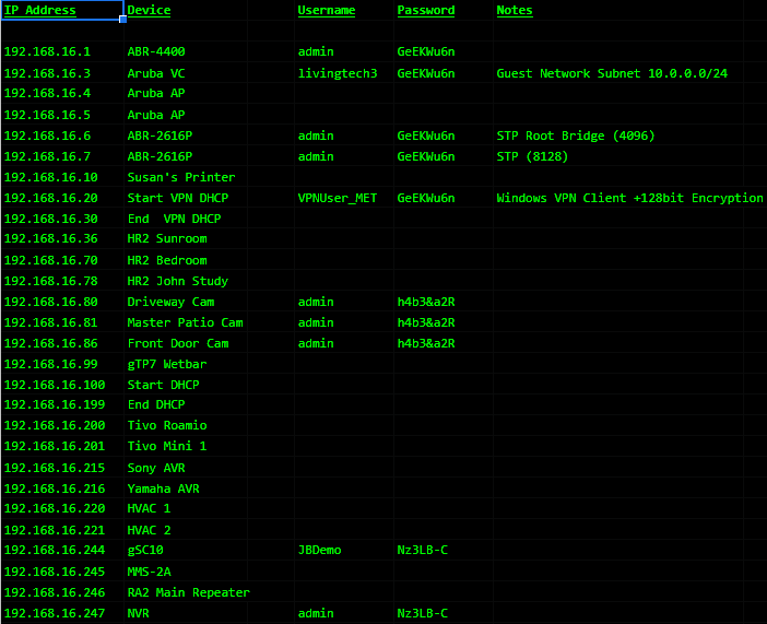
Notice on this sheet how it notates the start and end of the DHCP scope (192.168.16.100-192.168.16.199). It also lists each IP address that has a device statically assigned to it. For easy reference, it also lists the username and passwords of any devices that are password protected.
Planning networks become easier when allocate the IP addresses in a consistent way.
When I plan networks, I use the following scheme:
-
- Router/firewall is always at X.X.X.1.
- The range from X.X.X.2-X.X.X.9 are network switches
- The virtual controller for the WAP’s is always at 10.
- The WAP’s are always from 11-19.
- The NVR is always at 50.
- Cameras are always from 51-79.
- Thermostats are from 80-89
- Client’s office devices (printers, nas, etc) are from 90-99.
- DHCP Scope is from 100-199.
- TV’s are from 200-215
- Hand held remotes are from 216-229.
- AVRs and other zone controllers are 230-243.
- My Elan system controller is always at 244.
- My media servers are always 245-246.
- Other core home automation components are 247-253.
If the same scheme is used repeatedly, it will simplify adding the process of adding new devices. For example, if I want to add a WAP I can just scan the network and find the WAP with the highest IP, and just go to the next in line. I don’t have to worry about landing on the same IP as a remote, which might not be awake and responding when the network is scanned.
Another viable planning/documentation method would be to reserve all of the IP addresses for their associated device. Doing this, you would end up with a complete list in the router of all the devices and which IP addresses they are using. Using this method, it’s also recommended to reserve the addresses of the devices that have manually assigned IP addresses, just for the purpose of documenting the existence of the device.
Communication between devices on the same LAN.
Let’s start from scratch, and consider a scenario where there is a network switch with four devices connected to it. The IP addresses have been manually assigned, and the subnet mask set for 255.255.255.0 on all devices.
To demonstrate the communication process, let’s say that COMP 1 want’s to send a message to 192.168.1.29. Here’s a simplified process of how that happens:
Step 1: COMP 1 decides that 192.168.1.29 is part of the same local area network because it’s own IP address is 192.168.1.28 and the subnet mask is 255.255.255.0.
Step 2: COMP 1 sends a broadcast to the entire network asking, “Does anyone have the IP address 192.168.1.29?”
Step 3: COMP 2 replies, “Yes, I have the IP Address 192.168.1.29. You can reach me by using my physical address AB:CD:EF:22:22:22.”
Step 4: COMP 1 takes the message intended for COMP 2 and wraps it in a header that says “This message is from AB:CD:EF:11:11:11 and it needs to go to AB:CD:EF:22:22:22.”
Step 5: COMP 1 delivers the message to the network switch, which uses the included MAC address to route it to COMP 2, which is able to receive this message.
Notice that the destination IP address itself was not enough to send the message. That’s because network switches do not route packets based on IP addresses, they route them based on a table of MAC addresses. Therefore, any device that wants to send a message to any other device must first wrap that message with a header that includes that MAC address of the intended target.
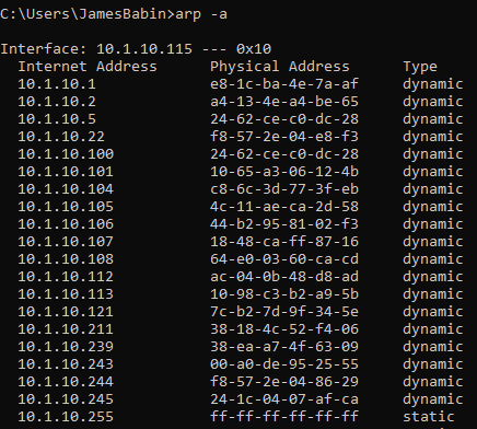
In step 2 of the above process, COMP 1 sent a broadcast to the entire network asking, “Does anyone have the IP address of 192.168.1.29?” This is called an ARP broadcast. It can skip this step next time, because it will remember to use the physical address AB:CD:EF:22:22:22 next time it needs to send information to that device. The list of corresponding IP Address/MAC Address combinations is called the “arp table.” As an exercise, on a Windows computer you can view the Arp table by opening a command prompt and typing “arp -a.”
Here is an example from my PC:
When a device sends an ARP broadcast, or when a device replies to an ARP broadcast with it’s physical address, the switch makes note of it. In our example, the switch notes that Port 1 has a device connected to it with the physical address AB:CD:EF:11:11:11 and Port 2 has the device AB:CD;EF:22:22:22. It keeps a table of ports and devices so that it will remember it for next time.
Here is an example from a Luxul network switch:
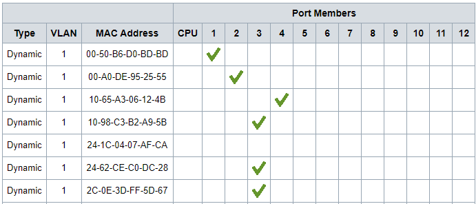
In the table above, you can see there are multiple MAC addresses assosciated with port 3. This is because port three goes to another, so all of the MAC addresses on the downstream switch will be listed on this single port.
This is the simplicity of a network switch. Take the frame, check the headers for the destination MAC address, and forward it to the right port. It keep getting forwarded from port to port, switch to switch, until it hits the target.
Managed network switches work the exact same way. The basic forwarding principal does not change. Layer 2/Layer 3 switches only add some granular control features to promote/inhibit this forwarding based upon other information provided in the same headers. With no special configuration, managed and unmanaged switches can generally be treated the same.
