DIY Prewire, Network
Low Voltage Wiring – Ethernet Network Jacks & Smart Home Devices
Mar
This is the third post in a series on low voltage wiring and structure cabling, and this one will cover prewiring your smart home devices. This will include in wall touch panels, lighting system repeaters, z-wave controllers, surveillance cameras, wireless access points, network, and phone jacks.
Purchase customized plans for a DIY Home Automation prewire.
How to Prewire Ethernet Network Jacks
We’ll start with network jacks because they are simplest and most straight forward. Everything else is virtually the same except for maybe the size of the back box and the type of cable you’re pulling. For ethernet network works, you’ll want to be pulling either Cat 5 or Cat 6 cable. There is literally no difference between these when it comes to the speed of your network unless you’re going over long distances, we’ll say more than 250′. However, the price difference is almost negligble anymore, and if you’re using Cat 6 for your video wire, you might as well use Cat 6 for your network too.
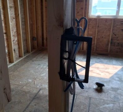
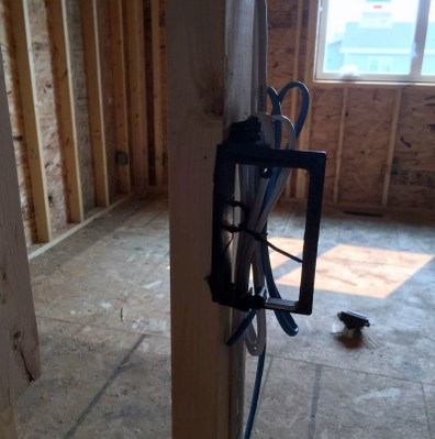
To start, pull a Cat 6 cable from the head end (usually the av equipment rack), and pull it to the jack location. Mount an open backed low voltage back at outlet height or at any other height that would make sense. Then, make sure the wire is stapled down the side directly in the middle, the last staple being just above the box. Leave enough wire to go through the box while having an addition 24″ of cable. Then, tie the cable into a nice small coil and fasten to the inside of the stud. Keep in mind that you must be able to cut the tie after drywall by sticking your hand through the box, so make sure it is easily accessible. Take care to make sure that the wire is not in any position to be cut by a roto zip during drywall, even if the drywaller to miss the box terribly. This is most easily accomplished by keeping all the wire in the direct middle of the stud space.
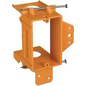
The primary image in this post is an example of how to properly tie the wire in order to avoid being cut while the drywall is being put up. The image below is another box very commonly used.
How to Prewire a Wireless Network Access Point
The cable pulling is the same as an ethernet network jack. Generally though, the boxes will be mounted in the ceiling, but this is assuming that you will be using a POE device. Not all wireless access points are made to mount to a single gang box, but most of the time they are large enough to cover, and you can eaven use one of the screw holes as one of your mounting points. If you are planning to use a very small device, then you can skip the box all together. Leave the wire dangling with about 36″ slack if you go this right, and use something to tie it into place. Leave a note for the drywallers saying something like “pull wire through drywall” and it should be all good.
If you are going to be using a wireless access point that does not support POE, then the wall is likely a more suitable choice. An outlet will be required though, so I recommend that the box be mounted at outlet height, and make sure it’s in close proximity to an outlet.
How to Prewire an In-Wall Touchpanel
Again, the same as a wireless network jack, with the exception of the box size and height. If the in-wall touch panel will likely have an LCD display, I prefer to mount these about 55″ from the ground. From here, all you need to do is determine the proper box size. Commonly in my designs I use the Elan gTP4 or gTP7 panels. The gTP4 takes a single gang back box while the gTP7 uses a double gang back box.
If you plan to use a different system, make sure that the touchpanels support POE. If they do NOT support POE then you should also run a 16/2 cable from the head end to the in-wall touch panel in order to provide power. This is the same wire I recommend using for speakers.
How to Prewire Security Cameras
Same concept as the ethernet network jack and touch panel if it is an IP Camera and supports POE, which most of the time is the case. Do NOT use any sort of back box when prewiring these devices. Simple leave the wire coming out of the exterior of the home, or ready to be pulled through the drywall. When you drill the hole outside, make sure to use a 1″ drill bit because you will need to be able to push the coupled ethernet RJ45 connector through the hole after the camera is mounted. It’s better this way. If you are drilling outside before surface materials are installed, the brick mason or siding guy needs to be instructed to do the same.
If they are analog cameras (why?) then pull an RG-59/18-2 siamese cable instead of the Cat 6. You could also just pull an individual RG-59 or RG-6 along with a 16/2 or 18/2 wire. It’s likely you’ll have these on the jobsite when doing the prewire, so there’s no need to use actual camera cable.
How to Pre-Wire Lutron Caseta & Z-Wave Devices
If using Lutron Caseta, or wiring for a Z-Wave Controller, we’re going to use the same method as descriped in the wireless access point section for devices that do NOT support POE. Use a Cat 6 cable, mount the box at outlet height, but be conscious that it will need to sit on top of or be hidden behind something. This should be the extent of wiring that needs to be pulled for these devices since the rest of the communication is all wireless.
How to Prewire for Lutron Radio RA2
I usually mount my Lutron Radio RA2 main repeaters close to the rack, but in a bedroom closet or something similar so that I can get a little bit more out of the range. We’ll wire these in teh same way that we wire for Caseta, but if there are auxilliary repeaters in the system then you’ll have a couple more wires to pull.
Lutron Radio RA2 auxilliary repeaters can communicate wirelessly, but this increases the necessary overlap of the wireless signal, so I always prefer to wire because you can get about another 1000′ out of them by placing them further away, or in remote locations like a garage. To prewire the Radio RA2 auxilliary repeaters we’ll use a cable that has 22/2 Shielded and 18/2 Unsheileded with the same jacket. I called this 22/2S+18/2. Here’s a picture of this cable.
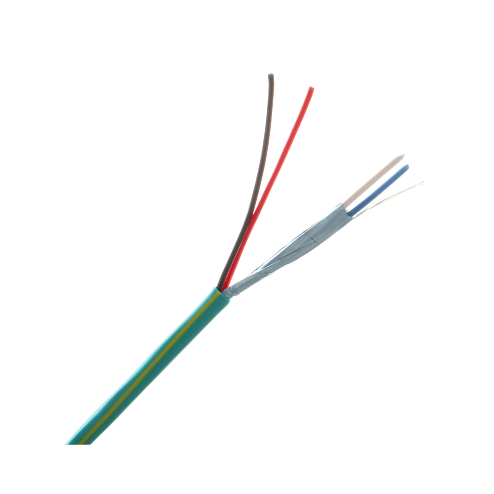
Pull one of these cables from the main repeater to the first Lutron Radio RA2 auxilliary repeater. Then pull another one from the first auxilliary repeater to the second, and so on. If you’re using 2 main repeaters (installations with over 100 devices), then make sure that each wire chain only has 3 auxilliary repeaters on it.
Let me know if I missed covering any devices.

Great, exploring the nuances of low voltage wire on this blog was truly enlightening. The insights into its versatility, energy efficiency, and safe usage are invaluable for anyone seeking to enhance their outdoor lighting and landscaping projects.